Friday, December 28, 2012

SEOS Project: Paint Prep

With the electronics on hold for a little while until I can get some components to test crossovers I went ahead with finishing up the cabinets.

The first step was filling in any gaps or blemishes using Bondo. Bondo is usually used for body work on cars, but it works well with MDF too, and I think it's easier to work with than wood filler.


Bondo is a two part mixture, with a base and a hardener. I used a less hardener than instructed so that I would have a longer working time to spread it. I mixed up a small amount and worked it into the gaps with a a putty knife. After about an hour or so, when it was fully hardened, I went back and sanded everything down flush. 

It often takes multiple passes with the Bondo to completely fill in large pits or gaps. Just be patient and make as many passes as you need to get a nice smooth finish.

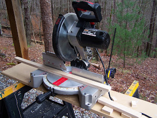
In between coats of Bondo, I got to work finishing up the bracing for the other two cabinets. I used a chop saw to cut my bracing material (leftover 3/4" Baltic Birch from my subwoofer project) slightly larger than the internal width of where they would be bracing. That way they could hold themselves in place for gluing, and securely brace the panels.


Once all the bracing was installed, and the final passes of Bondo were applied, I sanded down each cabinet up to 120 grit to smooth it down, but still give the paint some texture to adhere to. At this point I also knocked down the edges slightly. After cleaning the boxes with a damp cloth and letting them dry, I put on the first coat of primer.


Once the first coat of primer was dry, I used 220 grit sandpaper to smooth down any uneven primer before adding another coat. After the second (and final) coat of primer was applied, I also immediately sprayed some flat black enamel onto the driver cutouts, and the binding post recess in the back. The final topcoat will be rolled on (also flat black enamel), but the spray is easier to get into the tight spaces, and it should blend in fine. In any case, those areas will be mostly covered by the drivers. 


The next step is applying the first layer of topcoat. I'm letting the primer dry completely for a couple days before sanding it down and rolling on the topcoat.

Many thanks to Java of the AVS forum for his painting tips and tricks!

Tuesday, December 25, 2012

SEOS Project: Crossover Designs


Since measuring I've gotten to work on the crossover with a ton of help from tuxedocivic of the AVS forum, who kindly offered to gate the frequency response files and determine the acoustic offset to get me started. When determining the acoustic offset, we found that it was possible to match the shape of the curve from the parallel driver measurement, but that it was a couple dBs down from the summed response in PCD due to the individual driver measurements. Tuxedocivic suggested that it might be because the amp wasn't able to output enough current into the low impedance from the drivers in parallel.

Here's what the offset test looks like (the grey is the actual measured summed response, and the black is PCD's summed response based on the individual measurements):


To test that theory, tuxedocivic and I put in Bwaslo's crossover design as a reference point to see what was going on. With the z offset entered in PCD, there was a huge dip right around the crossover frequency that we knew wasn't from the crossover design, so tuxedocivic removed the offset, and the response was flat like it should be. (Just as a note, my measurements aren't the greatest, so I don't think it properly represents Bwaslo's crossover design. This was just used as a test to see if the offset was usable.)

Bwaslo's crossover with .06 z offset:

Bwaslo's crossover without z offset:

So that leaves the question of whether or not that dip actually exists in the system, or if it might be a result of not having enough amplifier for the measurements. Without knowing the answer, however, I just went ahead and played around in PCD to make a couple crossovers-- one taking the z offset into account, and one not.

Here are the results of my first crack at it:

Accounting for .06m z offset:

No z offset:

After showing these to tuxedocivic he pointed out that the one accounting for the acoustic offset definitely isn't a good option. Since the summed response is lower than the tweeter level near the crossover, just going slightly off axis can remove the phase cancellation in that area, and will result in a big ugly peak where it used to be flat. The one without the z offset, however, looks like it could work out, and it's actually a much simpler (and cheaper) crossover.

I've still got a lot of learning to do when it comes to crossover design, but I'll be putting together a mockup of the "no z offset" crossover to test. If everything goes right, and the z offset isn't actually that pronounced, it should look pretty good, and I'll probably go ahead with that design.

(note: all of these plots were created in Passive Crossover Designer 7, and the response below 250Hz is meaningless due to the gating used)

Saturday, December 8, 2012

SEOS Project: Measuring Drivers

Whew, it's been a while! I finally have an update, though. I got the chance to measure the drivers in the box so that I could get started working on the crossover. After acquiring the measurement equipment I needed, I got some guidance from bwaslo, and tuxedocivic from the AVS Forum on what measurements to take, and how to do it. They were a huge help, and I'm in their debt!

For my setup, I'm using my laptop along with a Tascam-US 122 mkII and a Dayton EMM-6 microphone. I took everything outside to a pool area that overlooks a field and a small lake, which should have been plenty of room to properly measure. I set the speaker atop a ladder and got to work.


First I got everything set up with the correct levels in REW, and made sure not to change any of the input or output settings on the Tascam, or the volume on the amp until I was done testing everything.

For the measurements, first I took a measurement of just the SEOS/DNA360, then just the 2512, then both in parallel. This is a set of measurements was taken without moving the speaker, the microphone, or changing any settings, and is used to set up the acoustic offset of the drivers as described here: https://www.box.com/shared/ouxjjsx0m8bs00cil5iq

Next, I took measurements of the waveguide and the woofer individually, and directly on axis for each one. I also measured each driver about 22 degrees off axis horizontally to simulate toe in, as per bwaslo's recommendation.

Here are the measurements for the acoustic offset:


These are the measurements from the tweeter level:


And these are the measurement from the woofer level:


The next step, and what I'm currently working on, is designing the crossover network by using this data in Passive Crossover Designer.