Sunday, March 31, 2013

SEOS Project: Finally done (for real this time)


As it turns out, my "final" crossover that I had decided upon from before was no good. The early bass rolloff that I was attributing to measurement error was actually a real problem, and I had to start again ) to try to rectify it. Below is the speaker without accounting for the rolloff in red, and the finished design in teal.


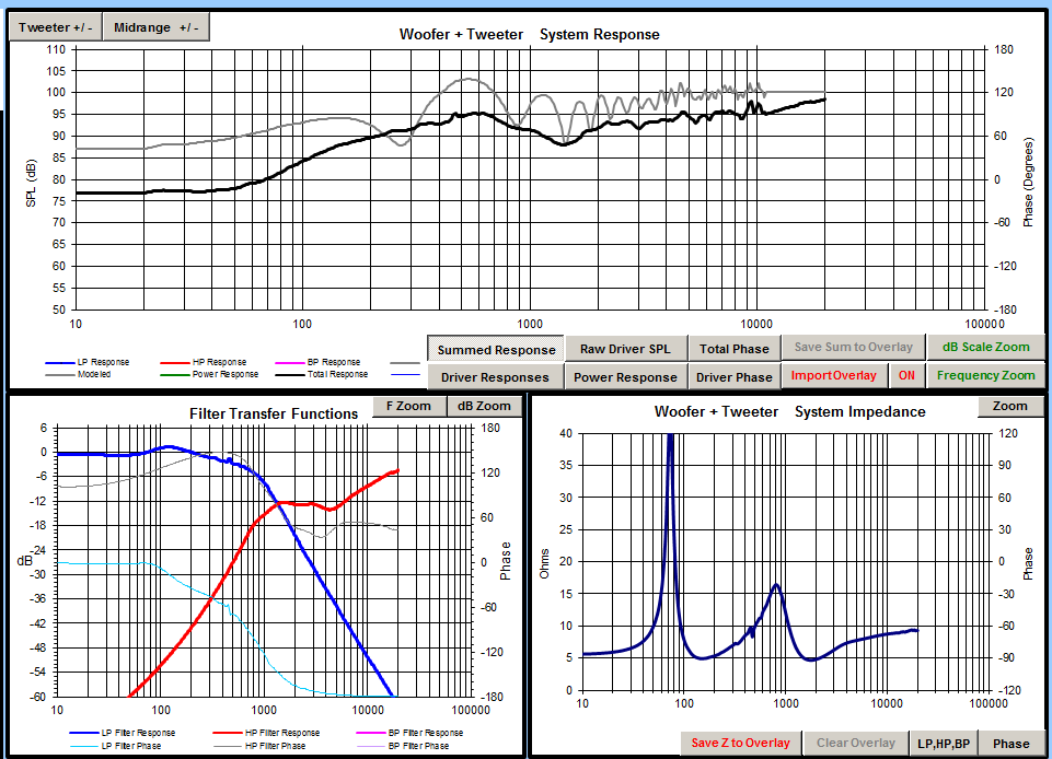
To do that, I started over with a much larger inductor on the low pass filter, which essentially lowered the cuttoff frequency, but since the response was rising for the woofer anyway I was able to end up with about the same crossover frequency as before.


Unfortunately, this decreases the overall sensitivity of the speaker, but I was willing to make that sacrifice for a more balanced frequency response.

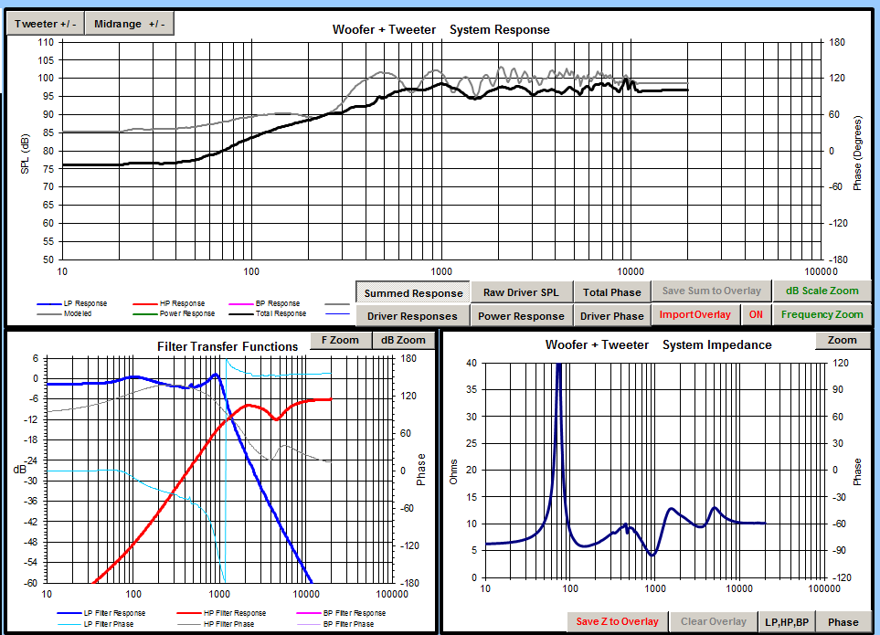
Here is the circuit that I came up with for the crossover:


It is a third order low pass on the woofer, with a first order high pass on the tweeter. The capacitor and resistor in parallel on the high pass make up an RC contour filter which adds a rising response to the upper frequencies. This was added to get a little bit more high frequency extension out of the tweeter which rolls off  a little early (15kHz or so) on its own. Finally, the series RLC circuit in parallel with the tweeter is a simple notch that is made to knock down a bump around 4kHz and flatten out the tweeter's response overall.

Below are measurements taken indoors at about four feet away. First is the horizontal off axis performance:


Next is the vertical off axis performance:


The hump at about 500Hz, and the dip at 225Hz both seem to be room related, since they appear in measurements of other speakers as well. I'll take some measurements outside when I get a chance.

Once the crossover design was finalized I ordered the parts, built up the crossovers, and installed them in the cabinets.


Above is the finished crossover, and below are the before and after pictures of the speakers in their final resting place in my current space. I'll put the third one to use once I move to a larger space.


The sound is phenomenal. These speakers don't even break a sweat at levels that will drive me out of the room, and the higher sensitivity means that my amplifier doesn't have to work as hard to do it. The added sensitivity and lower distortion also make them easier to listen to without discomfort at higher levels. Overall I'm very impressed, and glad to be enjoying these speakers that I've been working of for about eight months.

Many thanks to EricH of DIY Sound Group, as well as tuxedocivic and BWaslo of the AVS forums. Without their parts and assistance, this project wouldn't have happened.

Friday, March 8, 2013

SEOS Project: Crossover Design Finished


After a couple months, over a dozen crossover designs (see above), and many hours designing and measuring, I think I've finally come to the conclusion of this project.

When I left you last time, I was convinced that I had a good stopping point because I thought that the problems I was getting at 750-800Hz off axis were just a problem of the room, or some reflection off the wall I was inching toward as I moved the measurement microphone.


It turns out, that was not a problem of the room at all, and was due to some pretty serious phase cancellation off axis, a conclusion I came to after testing out Bwaslo's crossover design and measuring it. While his design didn't end up working for my particular case, it didn't exhibit the same issues in that area despite being placed in the same location in the room.


The low end doesn't look quite the same as the other measurements I've done, but I'm chalking that up to the weird problems I've been having intermittently with my measurement setup. Unfortunately, this design doesn't suit my driver arrangement (because of the z offset of the drivers), which can be seen in the image below, which plots the measured response (in gray) against the modeled crossover. Due to reflections in the room and differing levels the plots don't match up exactly, but they track each other pretty well. 


One thing I did like about this crossover was that it eeked out a little bit of extra extension in the high frequencies, so I set about trying to duplicate that with one of my crossovers that accounted for the acoustic offset of the drivers.


In the above image you can see the result of those efforts. I managed to get some of that extension, but at the expense of exaggerating the hump centered roughly around 6-7kHz. While this design was a failure at the time it may deserve a revisit, since I hadn't properly integrated a circuit that should have helped tame that bump.

After that failed design, I went ahead and tried to tackle the problem I had before with the null at 700-800Hz. Since I knew it was a phase cancellation problem, I played around with the orders of the high pass and low pass filters, to try to get each driver's phase as in line with each other as possible. Below is the model for the design that I finally settled upon, with the phase of the two drivers overlayed on the plot.


As you can see, the drivers stay within about 10-15 degrees of each other until the crossover at which point the tweeter has already taken over completely. This design ended up measuring very well, and despite the fact that it doesn't include the high frequency extension I was hoping for in the other design, I'm very happy with the outcome.

Below is the measured response along the horizontal axis:


Next is the vertical axis. There is a null as you move below the tweeter axis, but it's something I can live with. Ideally I'll have them set up so that the listening position is always on the tweeter axis vertically.


Finally is a comparison of the modeled response (in black), and the actual measured response (in grey).


I'll still do a little playing around with this design before I finalize it, but really all that's left is to order the crossover parts, and build up the boards before closing up the cabinets for good.