Showing posts with label eminence. Show all posts

Friday, March 8, 2013

SEOS Project: Crossover Design Finished


After a couple months, over a dozen crossover designs (see above), and many hours designing and measuring, I think I've finally come to the conclusion of this project.

When I left you last time, I was convinced that I had a good stopping point because I thought that the problems I was getting at 750-800Hz off axis were just a problem of the room, or some reflection off the wall I was inching toward as I moved the measurement microphone.


It turns out, that was not a problem of the room at all, and was due to some pretty serious phase cancellation off axis, a conclusion I came to after testing out Bwaslo's crossover design and measuring it. While his design didn't end up working for my particular case, it didn't exhibit the same issues in that area despite being placed in the same location in the room.


The low end doesn't look quite the same as the other measurements I've done, but I'm chalking that up to the weird problems I've been having intermittently with my measurement setup. Unfortunately, this design doesn't suit my driver arrangement (because of the z offset of the drivers), which can be seen in the image below, which plots the measured response (in gray) against the modeled crossover. Due to reflections in the room and differing levels the plots don't match up exactly, but they track each other pretty well. 


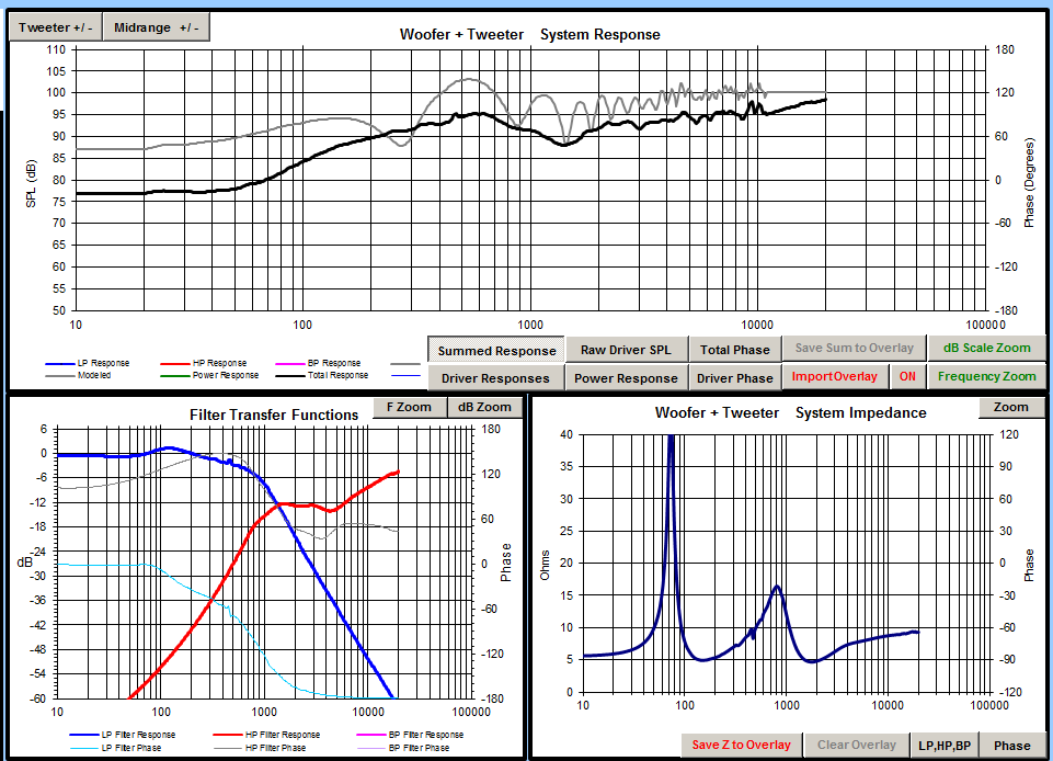
One thing I did like about this crossover was that it eeked out a little bit of extra extension in the high frequencies, so I set about trying to duplicate that with one of my crossovers that accounted for the acoustic offset of the drivers.


In the above image you can see the result of those efforts. I managed to get some of that extension, but at the expense of exaggerating the hump centered roughly around 6-7kHz. While this design was a failure at the time it may deserve a revisit, since I hadn't properly integrated a circuit that should have helped tame that bump.

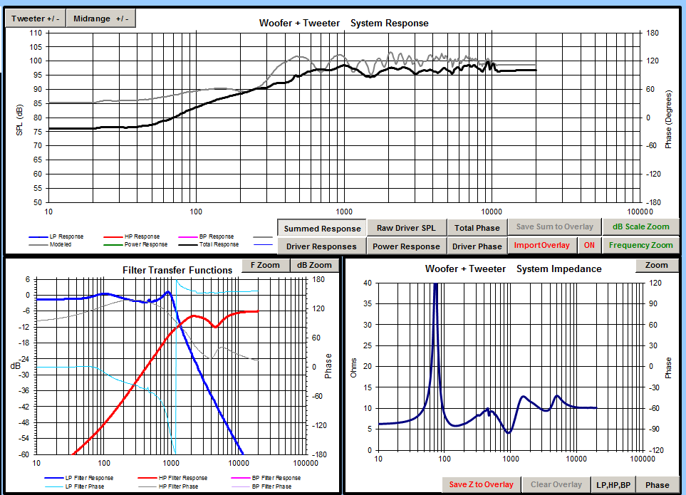
After that failed design, I went ahead and tried to tackle the problem I had before with the null at 700-800Hz. Since I knew it was a phase cancellation problem, I played around with the orders of the high pass and low pass filters, to try to get each driver's phase as in line with each other as possible. Below is the model for the design that I finally settled upon, with the phase of the two drivers overlayed on the plot.


As you can see, the drivers stay within about 10-15 degrees of each other until the crossover at which point the tweeter has already taken over completely. This design ended up measuring very well, and despite the fact that it doesn't include the high frequency extension I was hoping for in the other design, I'm very happy with the outcome.

Below is the measured response along the horizontal axis:


Next is the vertical axis. There is a null as you move below the tweeter axis, but it's something I can live with. Ideally I'll have them set up so that the listening position is always on the tweeter axis vertically.


Finally is a comparison of the modeled response (in black), and the actual measured response (in grey).


I'll still do a little playing around with this design before I finalize it, but really all that's left is to order the crossover parts, and build up the boards before closing up the cabinets for good.

Tuesday, February 26, 2013

SEOS Project: Crossover Design

Once the cabinets were completed, I set to designing the crossover, which I soon discovered was going to be a much more challenging task than I initially thought. My naive assumption that the physical crossover would perfectly match the modeled crossover was soon crushed, and I began the sometimes tedious, but mostly fun and interesting, process of designing and testing different crossover networks.

I quickly learned that the room I had available to me was going to present some problems since it is quite small, and not very well suited to the type of measurements I would be doing. With some help, I managed to get my measurements and clean them up in a way that gives me a reasonable idea of what's going on in the crossover region. Doing this required gating of the impulse response of the measurements, effectively removing the effects of signals delayed in time (mostly reflections that don't represent the direct signal from the speaker) at the cost of greatly reducing the frequency resolution of the data, and rendering the low frequency data (everything below about 250 Hz) useless, and unrepresentative of what's actually going on.

I started off with the design mentioned in the last post about the crossover that didn't take into account the acoustic offset derived from my previous measurements:


Omitting a small network on the tweeter's high pass filter, I was left with a fairly simple six component network that I was able to quickly prototype and implement in the finished cabinet. Below is the actual measured crossover from the above design:


As you can see, the actual crossover point is good deal lower than the modeled version, resulting in a more significant dip in the frequency response around the crossover point. On axis, this design doesn't actually look that terrible, despite the shifted crossover frequency, but with such a low crossover, the directivity of the woofer does not match that of the waveguide, resulting in poor off axis performance.

With my less than scientific documentation, I'm not entirely sure which crossover design the following screen captures represent, but I'm fairly certain they are a design very similar to the one shown above, but with the low pass filter altered to raise its cutoff frequency. It is the same kind of design, with a second order high pass on the tweeter, and a second order lowpass on the woofer, and it had similar behavior to the one pictured above, so I'll be using its measurements to show the off axis performance of the crossover.


The traces in the above picture, show the speaker at about 10 degree increments. Notice the large dips that appear at about 750 Hz and 1200 Hz as the microphone position moves further off axis. The null at 750 Hz has been present in other designs, and is possibly a result of reflections in the (less than ideal) room where I'm measuring, but the problem at 1200 Hz seems to be due to poor directivity and phase matching in the crossover region, which is possibly a result of the acoustic offset that I ignored for this particular design.

Even worse is the off axis performance in the vertical direction. When the microphone was placed between the tweeter and woofer, a huge null appeared, and was only slightly less at the woofer level.


The main point that these measurements seemed to suggest was that the acoustic offset of the two drivers is actually an issue, and not just an anomaly of the measurement setup I used to test the raw drivers. From this realization, I designed a very different crossover that took the offset into account, and ended up with better results.


This design uses a very simple first order high pass on the tweeter, and a third order low pass on the woofer, and manages to keep the crossover region flat in spite of the troubles caused by the acoustic offset of the drivers.


Shown above is the new design measured from varying heights. The response does get a little rocky around the crossover region, but it looks nothing like the deep null from the other design. 

Next is the horizontal off axis response of this design. As you can see, the null at 750 Hz is back with a vengeance, but the next plot shows the off axis performance from a different area of the room, which all but removes the problem, leading me to believe it was just a result of the reflections in the room.


Overall I'm happy with the measured performance, and sound of this design, so it will likely be the final choice. However, I would still like to test in a large space (outside preferably) before ordering any parts. Also I need to implement a simple LCR circuit in the tweeter's high pass to knock down the small bump at about 4 kHz and see how that effects everything.

Until I can do those things, my next step is to build Bwaslo's proven crossover and test that so I have something to compare to. This, above anything else, will help show if the acoustic offset is truly a problem, since it was designed without my particular offset in mind and should be flat if the offset doesn't exist. Additionally if it sounds good and measures well, I'll have an option if I decide to give up on this particular design and go with something already completed.

SEOS Project: Cabinets Complete

Around the beginning of the year, I finally completed the cabinets for the speakers, finishing the paint job, and adding some fiberglass insulation to dampen internal reflections.

The finishing was done with a 3/16" nap foam roller, and Rustoleum flat black enamel paint. Two coats were applied, with sanding in between using fine grit (320) sandpaper on a random orbital sander. The cutouts, and tight spaces, especially in the binding post recess, were painted using cheap foam brushes.


Lining the cabinets was the next step. I used standard R13 fiberglass insulation, cut it to size with a box cutter, and peeled off the backing before gluing it to the sides, top, and back of the cabinets.


Friday, December 28, 2012

SEOS Project: Paint Prep

With the electronics on hold for a little while until I can get some components to test crossovers I went ahead with finishing up the cabinets.

The first step was filling in any gaps or blemishes using Bondo. Bondo is usually used for body work on cars, but it works well with MDF too, and I think it's easier to work with than wood filler.


Bondo is a two part mixture, with a base and a hardener. I used a less hardener than instructed so that I would have a longer working time to spread it. I mixed up a small amount and worked it into the gaps with a a putty knife. After about an hour or so, when it was fully hardened, I went back and sanded everything down flush. 

It often takes multiple passes with the Bondo to completely fill in large pits or gaps. Just be patient and make as many passes as you need to get a nice smooth finish.

In between coats of Bondo, I got to work finishing up the bracing for the other two cabinets. I used a chop saw to cut my bracing material (leftover 3/4" Baltic Birch from my subwoofer project) slightly larger than the internal width of where they would be bracing. That way they could hold themselves in place for gluing, and securely brace the panels.


Once all the bracing was installed, and the final passes of Bondo were applied, I sanded down each cabinet up to 120 grit to smooth it down, but still give the paint some texture to adhere to. At this point I also knocked down the edges slightly. After cleaning the boxes with a damp cloth and letting them dry, I put on the first coat of primer.


Once the first coat of primer was dry, I used 220 grit sandpaper to smooth down any uneven primer before adding another coat. After the second (and final) coat of primer was applied, I also immediately sprayed some flat black enamel onto the driver cutouts, and the binding post recess in the back. The final topcoat will be rolled on (also flat black enamel), but the spray is easier to get into the tight spaces, and it should blend in fine. In any case, those areas will be mostly covered by the drivers. 


The next step is applying the first layer of topcoat. I'm letting the primer dry completely for a couple days before sanding it down and rolling on the topcoat.

Many thanks to Java of the AVS forum for his painting tips and tricks!

Tuesday, December 25, 2012

SEOS Project: Crossover Designs


Since measuring I've gotten to work on the crossover with a ton of help from tuxedocivic of the AVS forum, who kindly offered to gate the frequency response files and determine the acoustic offset to get me started. When determining the acoustic offset, we found that it was possible to match the shape of the curve from the parallel driver measurement, but that it was a couple dBs down from the summed response in PCD due to the individual driver measurements. Tuxedocivic suggested that it might be because the amp wasn't able to output enough current into the low impedance from the drivers in parallel.

Here's what the offset test looks like (the grey is the actual measured summed response, and the black is PCD's summed response based on the individual measurements):


To test that theory, tuxedocivic and I put in Bwaslo's crossover design as a reference point to see what was going on. With the z offset entered in PCD, there was a huge dip right around the crossover frequency that we knew wasn't from the crossover design, so tuxedocivic removed the offset, and the response was flat like it should be. (Just as a note, my measurements aren't the greatest, so I don't think it properly represents Bwaslo's crossover design. This was just used as a test to see if the offset was usable.)

Bwaslo's crossover with .06 z offset:

Bwaslo's crossover without z offset:

So that leaves the question of whether or not that dip actually exists in the system, or if it might be a result of not having enough amplifier for the measurements. Without knowing the answer, however, I just went ahead and played around in PCD to make a couple crossovers-- one taking the z offset into account, and one not.

Here are the results of my first crack at it:

Accounting for .06m z offset:

No z offset:

After showing these to tuxedocivic he pointed out that the one accounting for the acoustic offset definitely isn't a good option. Since the summed response is lower than the tweeter level near the crossover, just going slightly off axis can remove the phase cancellation in that area, and will result in a big ugly peak where it used to be flat. The one without the z offset, however, looks like it could work out, and it's actually a much simpler (and cheaper) crossover.

I've still got a lot of learning to do when it comes to crossover design, but I'll be putting together a mockup of the "no z offset" crossover to test. If everything goes right, and the z offset isn't actually that pronounced, it should look pretty good, and I'll probably go ahead with that design.

(note: all of these plots were created in Passive Crossover Designer 7, and the response below 250Hz is meaningless due to the gating used)

Saturday, December 8, 2012

SEOS Project: Measuring Drivers

Whew, it's been a while! I finally have an update, though. I got the chance to measure the drivers in the box so that I could get started working on the crossover. After acquiring the measurement equipment I needed, I got some guidance from bwaslo, and tuxedocivic from the AVS Forum on what measurements to take, and how to do it. They were a huge help, and I'm in their debt!

For my setup, I'm using my laptop along with a Tascam-US 122 mkII and a Dayton EMM-6 microphone. I took everything outside to a pool area that overlooks a field and a small lake, which should have been plenty of room to properly measure. I set the speaker atop a ladder and got to work.


First I got everything set up with the correct levels in REW, and made sure not to change any of the input or output settings on the Tascam, or the volume on the amp until I was done testing everything.

For the measurements, first I took a measurement of just the SEOS/DNA360, then just the 2512, then both in parallel. This is a set of measurements was taken without moving the speaker, the microphone, or changing any settings, and is used to set up the acoustic offset of the drivers as described here: https://www.box.com/shared/ouxjjsx0m8bs00cil5iq

Next, I took measurements of the waveguide and the woofer individually, and directly on axis for each one. I also measured each driver about 22 degrees off axis horizontally to simulate toe in, as per bwaslo's recommendation.

Here are the measurements for the acoustic offset:


These are the measurements from the tweeter level:


And these are the measurement from the woofer level:


The next step, and what I'm currently working on, is designing the crossover network by using this data in Passive Crossover Designer.

Sunday, October 7, 2012

SEOS Project: Box Construction Day 2

I started off the day by making a new, slightly smaller router base since the waveguide cutouts I was getting from my template were too small. Once that was fixed, I made a jig to align the front baffles underneath the template. Since the template is much larger than the baffle, I needed something to hold it up as I traced it, and also a way to make sure it was properly aligned on the baffle. To do this I took some scrap MDF and made a slot that I could slide the baffle into under the template. This made sure the template was aligned consistently for every cut and that the baffle didn't move. I simply clamped down the open end, and the baffle stayed put as I went to work with the router.


Below is what the baffle looked like after the first pass with the router. I made the recess about 5/16" deep and made sure to do the outline first. Then I went back in and chipped away around the edges until there was enough left over to seat the waveguide.


Next I used a jigsaw to make the rough cutout for the waveguide. It doesn't have to look pretty since the waveguide will cover it, so I made quick, rough cuts.


Once the waveguide holes were made, I got started on making the woofer cutouts. Comparatively these were extremely easy. Since I was using a 1/4" router bit, I had to make three separate passes, each one just smaller than the other to get down to the size where I would make the cutout.

First pass

Third pass

Final cutout
After all the cutouts were made, I went ahead and cut some more rings for the inside of the baffle. Since I cut about 1/3" for the recess I wanted to make sure there was plenty of stuff for the blind nuts to bite into on the backside. I did the same for the waveguide, but just cut some triangles for the corner. I originally meant for there to be a two layer baffle of 1/2" and 3/4" MDF, and had cut out the 1/2" pieces, until I realized that my flush-trim router bit only has a 1" cutting surface. A bit of an oversight, but I think this solution works perfectly well, and keeps the weight down a little.


Next up, I cut out some spare Baltic Birch to make some braces. These are 3/4" x 1 1/2", and are enough for all three cabinets. There will be two side to side braces, two front to back, and one top to bottom for each cabinet. After the boxes are complete I'll use a chopsaw to cut them to length and glue them in.


For the rings, I applied some glue, and rather than waste clamping time, I just shot it through with a few screws to hold it down while the glue dried. The glue is more than enough to hold it, but I'll leave the screws in.


I used a drill press to drill the holes for the mounting screws since I don't trust myself to drill the holes straight with a handrill and there isn't much space to work with.


Once the holes were drilled, I tapped in the hurricane nuts with a mallet after applying some Gorilla Glue to them. The nuts are supposed to hold themselves in, but I've spun my fair share of them, and it's no fun trying to fix it, so the expanding Gorilla Glue should do the trick. I'll also make sure to chase each one with a tap before trying to mount the drivers.


A row of finished baffles! The front baffle always takes up about 90% of the build time. The waveguide cutouts have 8/32 hurricane nuts, and the woofers have 10/32 nuts.


A quick test fit of the driver and waveguide in the front baffle. Looking good so far!


Clamping up the front and back. It's always a pain to get things aligned correctly, so I made them slightly larger than needed, so I can just trim them up with the flush trim bit and be done with it.