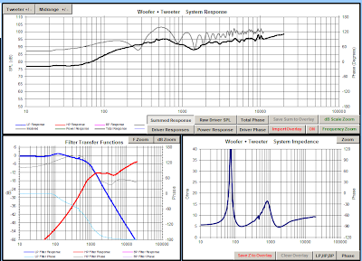
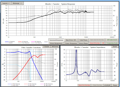
After a couple months, over a dozen crossover designs (see above), and many hours designing and measuring, I think I've finally come to the conclusion of this project.
When I left you last time, I was convinced that I had a good stopping point because I thought that the problems I was getting at 750-800Hz off axis were just a problem of the room, or some reflection off the wall I was inching toward as I moved the measurement microphone.
It turns out, that was not a problem of the room at all, and was due to some pretty serious phase cancellation off axis, a conclusion I came to after testing out Bwaslo's crossover design and measuring it. While his design didn't end up working for my particular case, it didn't exhibit the same issues in that area despite being placed in the same location in the room.
The low end doesn't look quite the same as the other measurements I've done, but I'm chalking that up to the weird problems I've been having intermittently with my measurement setup. Unfortunately, this design doesn't suit my driver arrangement (because of the z offset of the drivers), which can be seen in the image below, which plots the measured response (in gray) against the modeled crossover. Due to reflections in the room and differing levels the plots don't match up exactly, but they track each other pretty well.
One thing I did like about this crossover was that it eeked out a little bit of extra extension in the high frequencies, so I set about trying to duplicate that with one of my crossovers that accounted for the acoustic offset of the drivers.
In the above image you can see the result of those efforts. I managed to get some of that extension, but at the expense of exaggerating the hump centered roughly around 6-7kHz. While this design was a failure at the time it may deserve a revisit, since I hadn't properly integrated a circuit that should have helped tame that bump.
After that failed design, I went ahead and tried to tackle the problem I had before with the null at 700-800Hz. Since I knew it was a phase cancellation problem, I played around with the orders of the high pass and low pass filters, to try to get each driver's phase as in line with each other as possible. Below is the model for the design that I finally settled upon, with the phase of the two drivers overlayed on the plot.
As you can see, the drivers stay within about 10-15 degrees of each other until the crossover at which point the tweeter has already taken over completely. This design ended up measuring very well, and despite the fact that it doesn't include the high frequency extension I was hoping for in the other design, I'm very happy with the outcome.
Below is the measured response along the horizontal axis:
Next is the vertical axis. There is a null as you move below the tweeter axis, but it's something I can live with. Ideally I'll have them set up so that the listening position is always on the tweeter axis vertically.
Finally is a comparison of the modeled response (in black), and the actual measured response (in grey).
I'll still do a little playing around with this design before I finalize it, but really all that's left is to order the crossover parts, and build up the boards before closing up the cabinets for good.


No comments:
Post a Comment