Friday, December 28, 2012

SEOS Project: Paint Prep

With the electronics on hold for a little while until I can get some components to test crossovers I went ahead with finishing up the cabinets.

The first step was filling in any gaps or blemishes using Bondo. Bondo is usually used for body work on cars, but it works well with MDF too, and I think it's easier to work with than wood filler.


Bondo is a two part mixture, with a base and a hardener. I used a less hardener than instructed so that I would have a longer working time to spread it. I mixed up a small amount and worked it into the gaps with a a putty knife. After about an hour or so, when it was fully hardened, I went back and sanded everything down flush. 

It often takes multiple passes with the Bondo to completely fill in large pits or gaps. Just be patient and make as many passes as you need to get a nice smooth finish.

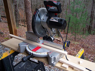
In between coats of Bondo, I got to work finishing up the bracing for the other two cabinets. I used a chop saw to cut my bracing material (leftover 3/4" Baltic Birch from my subwoofer project) slightly larger than the internal width of where they would be bracing. That way they could hold themselves in place for gluing, and securely brace the panels.


Once all the bracing was installed, and the final passes of Bondo were applied, I sanded down each cabinet up to 120 grit to smooth it down, but still give the paint some texture to adhere to. At this point I also knocked down the edges slightly. After cleaning the boxes with a damp cloth and letting them dry, I put on the first coat of primer.


Once the first coat of primer was dry, I used 220 grit sandpaper to smooth down any uneven primer before adding another coat. After the second (and final) coat of primer was applied, I also immediately sprayed some flat black enamel onto the driver cutouts, and the binding post recess in the back. The final topcoat will be rolled on (also flat black enamel), but the spray is easier to get into the tight spaces, and it should blend in fine. In any case, those areas will be mostly covered by the drivers. 


The next step is applying the first layer of topcoat. I'm letting the primer dry completely for a couple days before sanding it down and rolling on the topcoat.

Many thanks to Java of the AVS forum for his painting tips and tricks!

Tuesday, December 25, 2012

SEOS Project: Crossover Designs


Since measuring I've gotten to work on the crossover with a ton of help from tuxedocivic of the AVS forum, who kindly offered to gate the frequency response files and determine the acoustic offset to get me started. When determining the acoustic offset, we found that it was possible to match the shape of the curve from the parallel driver measurement, but that it was a couple dBs down from the summed response in PCD due to the individual driver measurements. Tuxedocivic suggested that it might be because the amp wasn't able to output enough current into the low impedance from the drivers in parallel.

Here's what the offset test looks like (the grey is the actual measured summed response, and the black is PCD's summed response based on the individual measurements):


To test that theory, tuxedocivic and I put in Bwaslo's crossover design as a reference point to see what was going on. With the z offset entered in PCD, there was a huge dip right around the crossover frequency that we knew wasn't from the crossover design, so tuxedocivic removed the offset, and the response was flat like it should be. (Just as a note, my measurements aren't the greatest, so I don't think it properly represents Bwaslo's crossover design. This was just used as a test to see if the offset was usable.)

Bwaslo's crossover with .06 z offset:

Bwaslo's crossover without z offset:

So that leaves the question of whether or not that dip actually exists in the system, or if it might be a result of not having enough amplifier for the measurements. Without knowing the answer, however, I just went ahead and played around in PCD to make a couple crossovers-- one taking the z offset into account, and one not.

Here are the results of my first crack at it:

Accounting for .06m z offset:

No z offset:

After showing these to tuxedocivic he pointed out that the one accounting for the acoustic offset definitely isn't a good option. Since the summed response is lower than the tweeter level near the crossover, just going slightly off axis can remove the phase cancellation in that area, and will result in a big ugly peak where it used to be flat. The one without the z offset, however, looks like it could work out, and it's actually a much simpler (and cheaper) crossover.

I've still got a lot of learning to do when it comes to crossover design, but I'll be putting together a mockup of the "no z offset" crossover to test. If everything goes right, and the z offset isn't actually that pronounced, it should look pretty good, and I'll probably go ahead with that design.

(note: all of these plots were created in Passive Crossover Designer 7, and the response below 250Hz is meaningless due to the gating used)

Saturday, December 8, 2012

SEOS Project: Measuring Drivers

Whew, it's been a while! I finally have an update, though. I got the chance to measure the drivers in the box so that I could get started working on the crossover. After acquiring the measurement equipment I needed, I got some guidance from bwaslo, and tuxedocivic from the AVS Forum on what measurements to take, and how to do it. They were a huge help, and I'm in their debt!

For my setup, I'm using my laptop along with a Tascam-US 122 mkII and a Dayton EMM-6 microphone. I took everything outside to a pool area that overlooks a field and a small lake, which should have been plenty of room to properly measure. I set the speaker atop a ladder and got to work.


First I got everything set up with the correct levels in REW, and made sure not to change any of the input or output settings on the Tascam, or the volume on the amp until I was done testing everything.

For the measurements, first I took a measurement of just the SEOS/DNA360, then just the 2512, then both in parallel. This is a set of measurements was taken without moving the speaker, the microphone, or changing any settings, and is used to set up the acoustic offset of the drivers as described here: https://www.box.com/shared/ouxjjsx0m8bs00cil5iq

Next, I took measurements of the waveguide and the woofer individually, and directly on axis for each one. I also measured each driver about 22 degrees off axis horizontally to simulate toe in, as per bwaslo's recommendation.

Here are the measurements for the acoustic offset:


These are the measurements from the tweeter level:


And these are the measurement from the woofer level:


The next step, and what I'm currently working on, is designing the crossover network by using this data in Passive Crossover Designer.

Sunday, October 7, 2012

SEOS Project: Box Construction Day 2

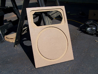
I started off the day by making a new, slightly smaller router base since the waveguide cutouts I was getting from my template were too small. Once that was fixed, I made a jig to align the front baffles underneath the template. Since the template is much larger than the baffle, I needed something to hold it up as I traced it, and also a way to make sure it was properly aligned on the baffle. To do this I took some scrap MDF and made a slot that I could slide the baffle into under the template. This made sure the template was aligned consistently for every cut and that the baffle didn't move. I simply clamped down the open end, and the baffle stayed put as I went to work with the router.


Below is what the baffle looked like after the first pass with the router. I made the recess about 5/16" deep and made sure to do the outline first. Then I went back in and chipped away around the edges until there was enough left over to seat the waveguide.


Next I used a jigsaw to make the rough cutout for the waveguide. It doesn't have to look pretty since the waveguide will cover it, so I made quick, rough cuts.


Once the waveguide holes were made, I got started on making the woofer cutouts. Comparatively these were extremely easy. Since I was using a 1/4" router bit, I had to make three separate passes, each one just smaller than the other to get down to the size where I would make the cutout.

First pass

Third pass

Final cutout
After all the cutouts were made, I went ahead and cut some more rings for the inside of the baffle. Since I cut about 1/3" for the recess I wanted to make sure there was plenty of stuff for the blind nuts to bite into on the backside. I did the same for the waveguide, but just cut some triangles for the corner. I originally meant for there to be a two layer baffle of 1/2" and 3/4" MDF, and had cut out the 1/2" pieces, until I realized that my flush-trim router bit only has a 1" cutting surface. A bit of an oversight, but I think this solution works perfectly well, and keeps the weight down a little.


Next up, I cut out some spare Baltic Birch to make some braces. These are 3/4" x 1 1/2", and are enough for all three cabinets. There will be two side to side braces, two front to back, and one top to bottom for each cabinet. After the boxes are complete I'll use a chopsaw to cut them to length and glue them in.


For the rings, I applied some glue, and rather than waste clamping time, I just shot it through with a few screws to hold it down while the glue dried. The glue is more than enough to hold it, but I'll leave the screws in.


I used a drill press to drill the holes for the mounting screws since I don't trust myself to drill the holes straight with a handrill and there isn't much space to work with.


Once the holes were drilled, I tapped in the hurricane nuts with a mallet after applying some Gorilla Glue to them. The nuts are supposed to hold themselves in, but I've spun my fair share of them, and it's no fun trying to fix it, so the expanding Gorilla Glue should do the trick. I'll also make sure to chase each one with a tap before trying to mount the drivers.


A row of finished baffles! The front baffle always takes up about 90% of the build time. The waveguide cutouts have 8/32 hurricane nuts, and the woofers have 10/32 nuts.


A quick test fit of the driver and waveguide in the front baffle. Looking good so far!


Clamping up the front and back. It's always a pain to get things aligned correctly, so I made them slightly larger than needed, so I can just trim them up with the flush trim bit and be done with it.


Friday, October 5, 2012

SEOS Project: Box Construction Day 1

I woke up this morning to get started cutting some wood for the speakers, and found a great surprise. My parents are celebrating my birthday early since I won't be home on the actual day, and when I walked into the garage I was greeted with this:


I haven't had a chance to use the orbital sander just yet, but table saw has already proven to be worth its weight in gold. When it come to making repeatable cuts, nothing beats a table saw, and this made short work of the cuts that I had to do. Thankfully when I went to Home Depot, a helpful employee cut a couple 15" panels out of the full 4'x8' piece on the panel saw, which also significantly cut down on my work.


Before making any cuts I did a few checks to make sure the saw was properly aligned. I measured from one of the teeth on the blade to the fence, then rotated the blade until the tooth was at the back of the blade and measured again.

Since the measurement was the same, the blade was well aligned with the fence, and I got started on making the cuts.


There was a small setback, since I found that I had misjudged the sizes of my material, and I'm currently short one 19 1/2" x 14 1/2" side pieces. I'll get some more MDF when I get the chance, and cut that last piece.

Once everything was cut out I clamped up the sides and the top and bottom for one cabinet, leaving a bit to hang over on the top and bottom so they could be trimmed flush with a router later.


While the glue was setting up, I got started making the template for cutting out the recess for the waveguide. I followed the instructions in this post on flush mounting irregularly shaped drivers and started by making the larger router base. In the picture below is the circle jig I made for my router, including the incorrectly measured hole for the cutout.


Without thinking, I measured to the far end of the bit, which resulted in an exactly 6 1/4" diameter hole, and a 1/2" smaller cutout, so I remeasured and finally cut out the 6 1/4" disk I would go on to use as the larger router base.


Once the larger router base was cut, I put the original base back on. Next I screwed the waveguide into the MDF (this time 1/4" thick) and traced around it with the router to make the template.


With the angle on the edge of the waveguide, the router base ended up tracing a little too close and made the template slightly too small, so I'm going to cut out a slightly smaller custom router base which will make the final cutout larger. Tomorrow I should be able to finish up the front baffle and hopefully close up one of the boxes.

Thursday, October 4, 2012

SEOS Project: Preparing to make sawdust

With both drivers in hand, I got started taking some measurements needed to being work on the enclosure and the crossover. First I measured the impedance curve for the Eminence Deltalite-II 2512 in open air and on a 1 cubic foot box. The equipment in the lab output a text file with the impedance data that I imported into REW to produce these graphs:

Off Box

On 1 ft^3 Box

REW also has a handy tool that will derive the driver parameters from the impedance graphs, so using that I got the following parameters:

TS Parameters file
Room EQ V5.01
Dated: Oct 3, 2012 8:29:47 PM
From measurement Eminence 2512 off box.
Zmin 5.41 ohm
fmin 213 Hz
f3 1036 Hz
Le(f3) 0.508 mH
Motional impedance parameters
RES 137.61 ohm
LCES 35.003 mH
CMES 373.5 uF
RAMS 137608.424 mohm
Blocked impedance parameters
RDC 4.50 ohm
dR 0.26 ohm
Re 4.76 ohm
Leb 131.0 uH
Le 2.001 mH
Rss 1503.6 ohm
Ke 0.0619 S-H
Thiele-Small parameters
fs 43.5 Hz
Qms 4.355
Qes 0.485
Qts 0.437
Fts 99.6
Mms 61.15 g
Cms 0.219 mm/N
Rms 3.836 kg/s
Vas 83.90 litres
Bl 12.796 Tm
Eta 1.39 %
Lp (1W/1m) 93.58 dB
Dd 25.72 cm
Sd 519.5 cm^2
Vb 28.317 litres
Secondary measurement: Eminence 2512 on box 1
Air temperature 20.0 C
Air pressure 1013.25 mB
Air density 1.2041 kg/m^3
Speed of sound 343.2 m/s

The data seemed quite different from the published specs (2512 Specs), but when I modeled it in WinISD, there actually wasn't a huge difference.

Below are the modeled system responses for both the published specs, and the measured parameters with a single driver in a 2 cubic foot box. I opted to go for a sealed box for several reasons: I'd like to keep the size manageable, going sealed simplifies the box construction, and finally since I plan to cross these over with subwoofers, I get plenty of extension (70ish Hz) for that purpose.

Going ported would allow a flat response down to around 40 Hz, which still wouldn't be full range, so subwoofers would be needed, and the crossover would be around 80 Hz anyway, essentially wasting the low frequency extension gained with the ported design.


Yellow: Given  Blue: Measured

Once the size of the box was chosen I went ahead and played around with the Enclosure Volume Calculator to arrive at the final dimensions. The only starting dimension was 15" wide for the front baffle to fit the SEOS waveguide with a little room to spare. I could have made it much taller and less deep, but it still wouldn't be tall enough to be floorstanding, and I'd rather just make stands for them later anyway. The .2 cubic feet entered for the driver volume is a rough estimate of the woofer, waveguide, and bracing. The final volume will not be exactly 2 cubic feet, but I tried to err on the larger side, since a slightly larger box will give a little more extension.


Finally, with the dimensions in hand I made up a cut list using a free program aptly named Cut List. It will try to find the most material efficient layout of panels, which can be nice, but in this case I just entered the panels and manually arranged them (which can be done just as easily with a sheet of paper and a pencil). I laid out the panels so that I could rip down the material and make sure that all of the panels had the same width (especially the 14 1/2" pieces since they must be identical). The 15" pieces aren't as critical since they'll be going on the front and back and I can just trim them with a flush-cut router bit.


Finally, I had to decide on what type of material to use. I'm very fond of the Baltic Birch plywood I used for my subwoofer project, since it's extremely strong, void-free, and fairly lightweight. It also has some decent looking grain, so with a little finishing work it provides a handsome natural wood finish. However, since these speakers will eventually go in a home theater (hopefully with a projector) they're going to get a more functional-- and less flashy-- matte black paintjob to reduce light reflections. And there isn't much that takes paint better than MDF, so that's the material I'll be going with. I'm not a fan of the ridiculous dust from the stuff, though, so I'll probably be picking up a respirator or at least a heavy duty dust mask when I go to the hardware store.

Thursday, September 20, 2012

SEOS Project: Waveguides are here!


Since the last post I've been waiting for the compression drivers and waveguides to arrive so that I can get started measuring and modeling the speakers, but to pass the time I've been doing some research about constant directivity loudspeakers, and the kinds of tools I'll be using to help me design them.

The Pi Speakers Whitepaper was the first source I looked at to get a sense of what's going on in a constant directivity system. It starts off with some background on horns and waveguides, and what kind of advancements led them to their current form, then it gets into how to integrate them into a two-way loudspeaker system. There is actually a lot more to consider when designing the crossover for a constant directivity system than just passing the correct frequencies to each driver. Since the goal is, of course, constant directivity, that means matching the directivity of the woofer to that of the tweeter at the crossover frequency, which adds a considerable amount of complexity.

Thankfully there are lots of resources available when it comes to crossover design. Next up on my reading list is also from Pi Speakers, and it's referred to as the Crossover Document. At over 70 pages, it's a hefty read, but I'm hoping it will expand upon what I've already picked up from Leach's Introduction to Electroacoustics and Audio Amplifier Design.

In addition to reading up on theory, I've been scouting out some programs to help me measure the drivers, design the crossover, and model the final system before spending any money on crossover components. Here's what I've found so far:

Room EQ Wizard (REW): I've used this in the past for measuring the in-room frequency response of my subwoofers, but it also has the option to measure driver impedance and spit out parameters for use in modeling software.

WinISD: Using the driver parameters, this program models the transfer function of the driver in different enclosures.

Passive Crossover Designer 7 (PCD): This program takes in raw impedance and frequency response data from each driver, and allows you to design and model a crossover while providing graphs for frequency response (at any position in relation to the system) and directivity. This program will also model different enclosures and can use that data for the crossover design.


Finally, last but not least, my compression drivers and waveguides just arrived today. The waveguides are made out of extremely thick and heavy plastic, and feel incredibly solid, although next to the compression drivers, they're lightweights. The DNA-360 is a monster! These things are much larger and heavier than I expected, and I wouldn't be surprised if the CD/waveguide combo weighed more than the woofers do. For some size reference, here's a picture of me holding one of them.